Was: 11.25
Price: 8.99
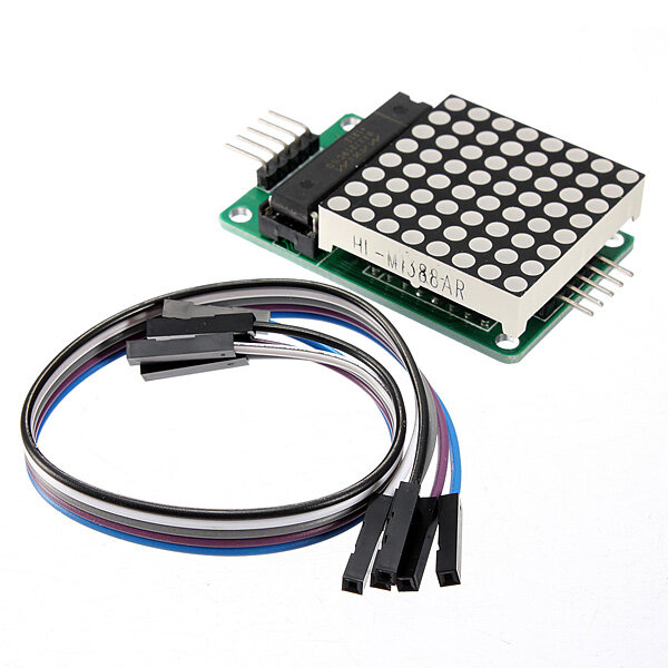
Specifications A single module can drive an 8 x 8 common cathode latticeOperating voltage 5VSize 5 x 3 2 x 1 5 cm L x W x H LED color RedWith four screws hole aperture 3mmWith input and output interfaces supports multiple modules cascadeWiring instructions 1 The module left side as an input port and the output port on the right2 To control a single module just connect the input port to the CPU3 When cascading multiple modules the input port of the first module connect to the CPU the output port connect to the input port of the second one and so on In the case of 51 MCU VCC → 5VGND → GNDDIN → P22CS → P21CLK → P20Note 1 VCC and GND is not reversed it would burn the chip 2 When the 51 microcontroller P0 port controlling must be connected to the pull up resistor it is recommended that the resistance of 4 7K 10K3 Please install lattice into the round hole first and then insert the round hole to PCB board and weld Face the side of lattice with words from left to right pin order is 123456 PCB board 1st pin is square pad 4 Electrolytic capacitors long pin as positive short pin as negative ceramic capacitor hsa no positive and negative pointsPackage included 3 x LED module3 x Dupont line 5P 20cm
https://ad.admitad.com/g/e8f129b05ed12a4616dd6213826a88/?f_id=19362&ulp=https%3A%2F%2Fwww.banggood.com%2F3Pcs-MAX7219-Dot-Matrix-Module-MCU-LED-Control-Module-Kit-Geekcreit-for-Arduino-products-that-work-with-official-Arduino-boards-p-1031710.html%3Fcurrency%3DEUR&i=5


Leave a Reply